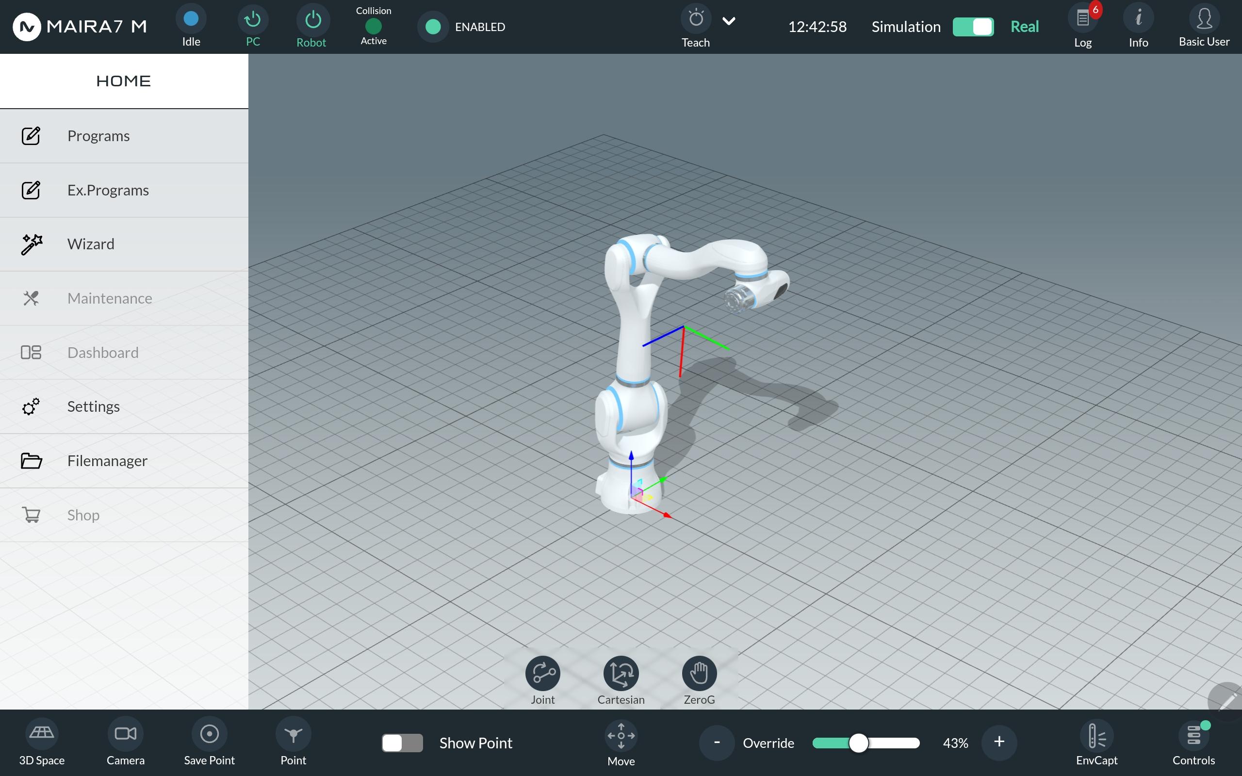
Graphical User Interface
Wizards
Wizards assist users in setting up and enhancing the robot’s AI functionalities on the robot. To access the available wizards, navigate to HOME > WIZARD.
Dynamic Parameter Identification (DPI)
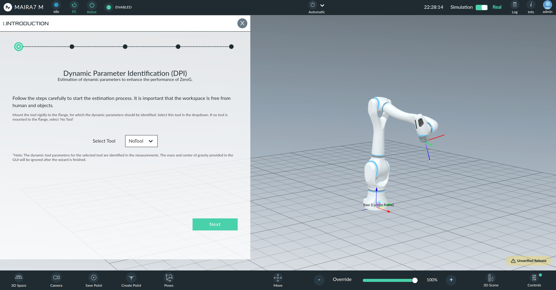
The Dynamic Parameter Identification (DPI) wizard helps identify the robot’s dynamic parameters by conducting a real-world experiment. This tool can be used to improve ZeroG mode, enhance collision detection robustness, or identify dynamic tool parameters.
- The robot will perform two motions to gather data from its internal sensors, then recalibrate its dynamic parameters.
Make sure to read the instructions in every step of the DPI wizard. Follow the detailed instructions.
During DPI, collision detection is deactivated. Ensure the workspace is free of obstacles and humans.
DPI is not a collaborative mode, and a password is required to execute the wizard. The operator is responsible for ensuring safety.
Warning
Always ensure the Emergency-Stop-Button within reach! Keep an eye on the robot to avoid collisions with itself, the tool, humans, or the environment. Start with low velocities, and only increase them once you feel confident that the robot is operating safely.
Tutorial
When performing DPI with a tool mounted, the tool’s parameters will be incorporated into the robot’s flange. Ensure that the tool settings are set to zero before performing DPI to prevent altering the robot’s dynamic behavior. Non-zero values will be added to the identified parameters after the DPI and might change the dynamic behavior of the robot.
Note
The trajectory also accounts for a tool of 30cm x 30cm x 25cm to avoid self-collisions with a mounted tool.
The 3D visualization in the GUI should now reflect the robot’s pose, similar to its real-world position.
Important
It’s crucial to warm up the robot for at least 20 minutes (1 hour recommended) before performing DPI. If DPI is conducted without warming up, the results may be compromised, affecting ZeroG mode and collision detection.
Start the DPI Wizard by entering the password and tab next.
To start the motion of the robot, Automatic Mode is needed.
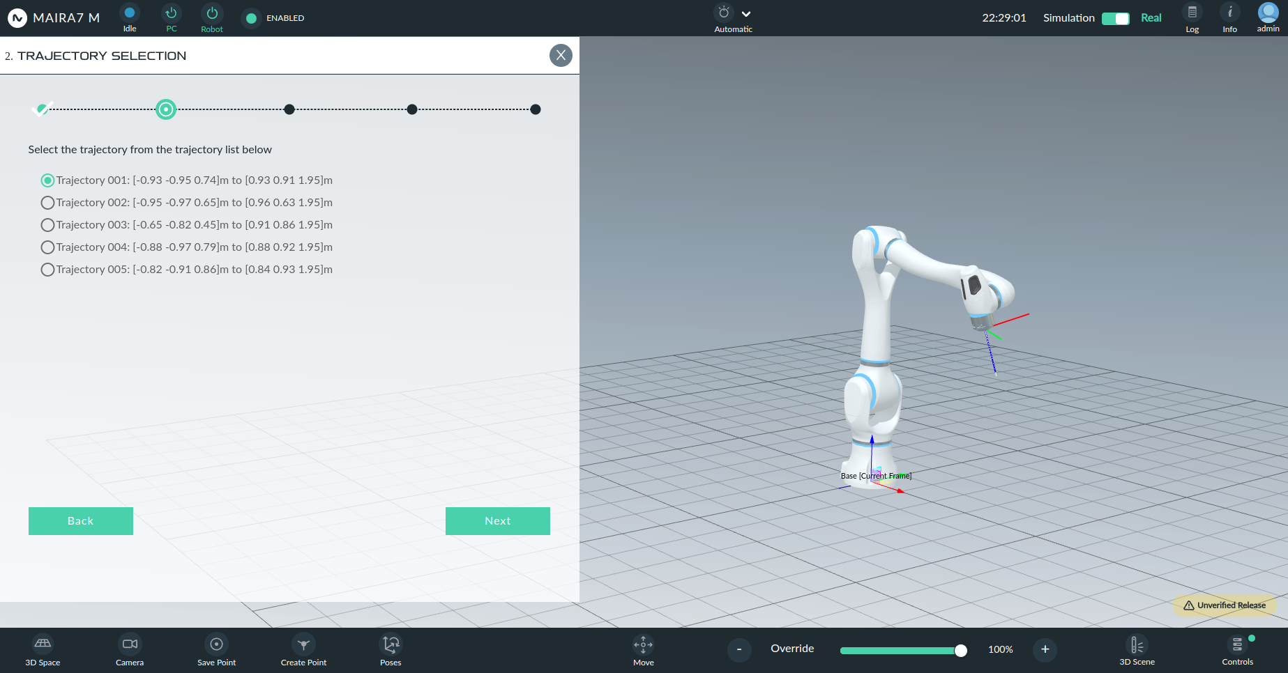
- The wizard consists of three main steps:
One Slow test run (20% speed) to ensure the robot does not collide with surroundings. Be ready to stop the robot at any time during this run.
One full speed run to collect sensor data using the same trajectory at full speed.
Evaluation of the data & reloading of the parameters.
The robot will perform a rapid motion along the positive x- and z-planes of its base frame (in front of the robot). Ensure that the robot has sufficient space to perform the identification trajectory.
DPI also considers Global Settings regarding the joint range limits. Running DPI is not possible when the limits are too restrictive. (Warning will be shown.)
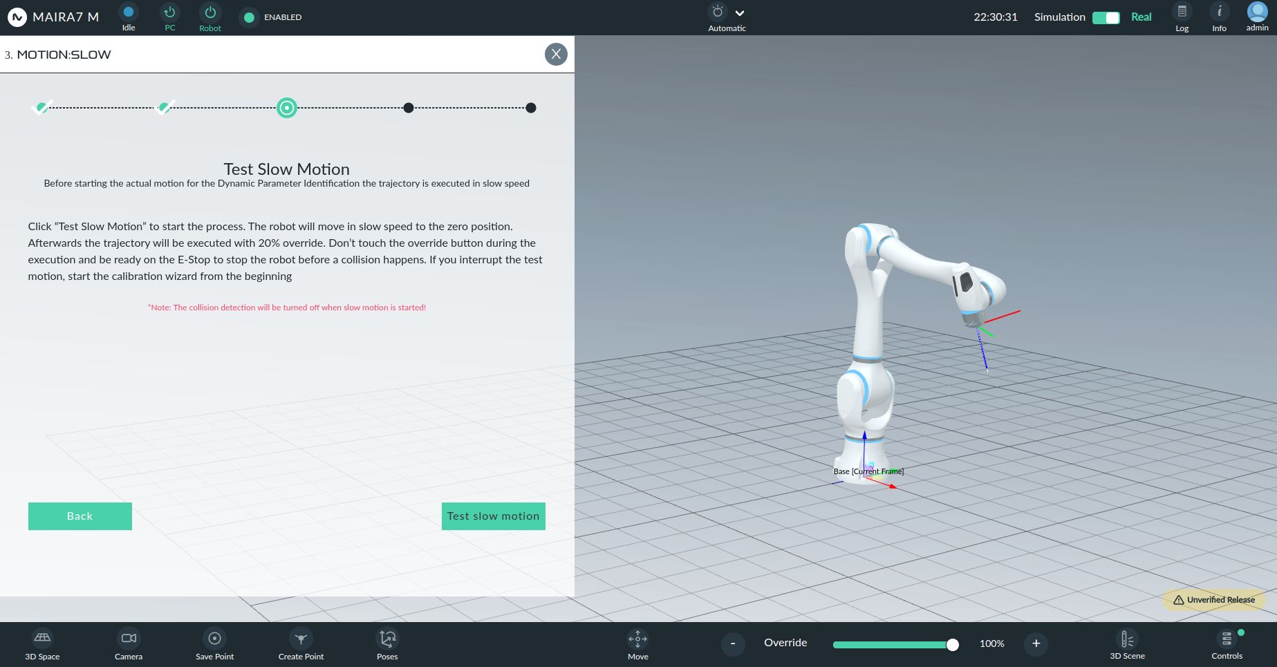
After the execution of the wizard, the new parameters are loaded automatically, and collision detection is turned on again.
- Dynamic Parameter Identification can also be used to identify unknown tool dynamic parameters:
After running DPI, the previous parameters are overwritten and lost. Currently, we recommend backing up the parameters via NeuraUSB, and reinserting them if desired.
When unmounting the tool, the operator needs to upload the parameters again via NeuraUSB or perform DPI again.
- Performing DPI is recommended in the following situations:
Unavailability or difficulty to find the correct tool parameters.
Unsatisfying robustness of the collision detection.
Improving hand-guiding smoothness for ZeroG Mode.
Change of environmental temperature.
Note
After performing DPI, perform a simple validation check of the ZeroG mode, and eventually adjust the friction and holding torque sliders.
Hand-Eye Calibration
Introduction
The Hand-Eye Calibration Wizard is designed to compute the static transform between a camera and a robot through a user-friendly and intuitive process.
This wizard supports two configurations:
Hand-in-Eye (Internal): Camera is mounted on the robot.
Hand-to-Eye (External): Camera is static, and a calibration marker is mounted on the robot.
Process Overview
Navigate to the Wizard tab from the left sidebar.
Select the Hand-Eye Calibration wizard.
Use the wizard to either:
Create a new hand-eye calibration.
View existing hand-eye calibrations.
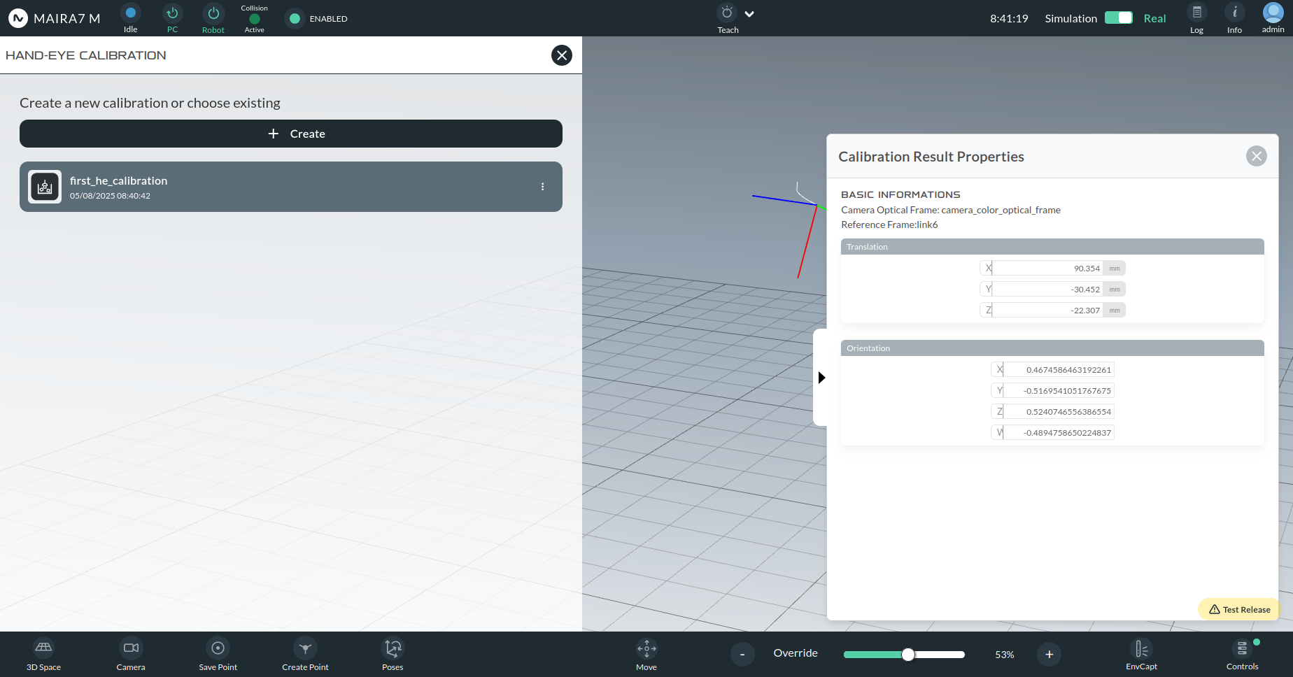
Creating a New Calibration
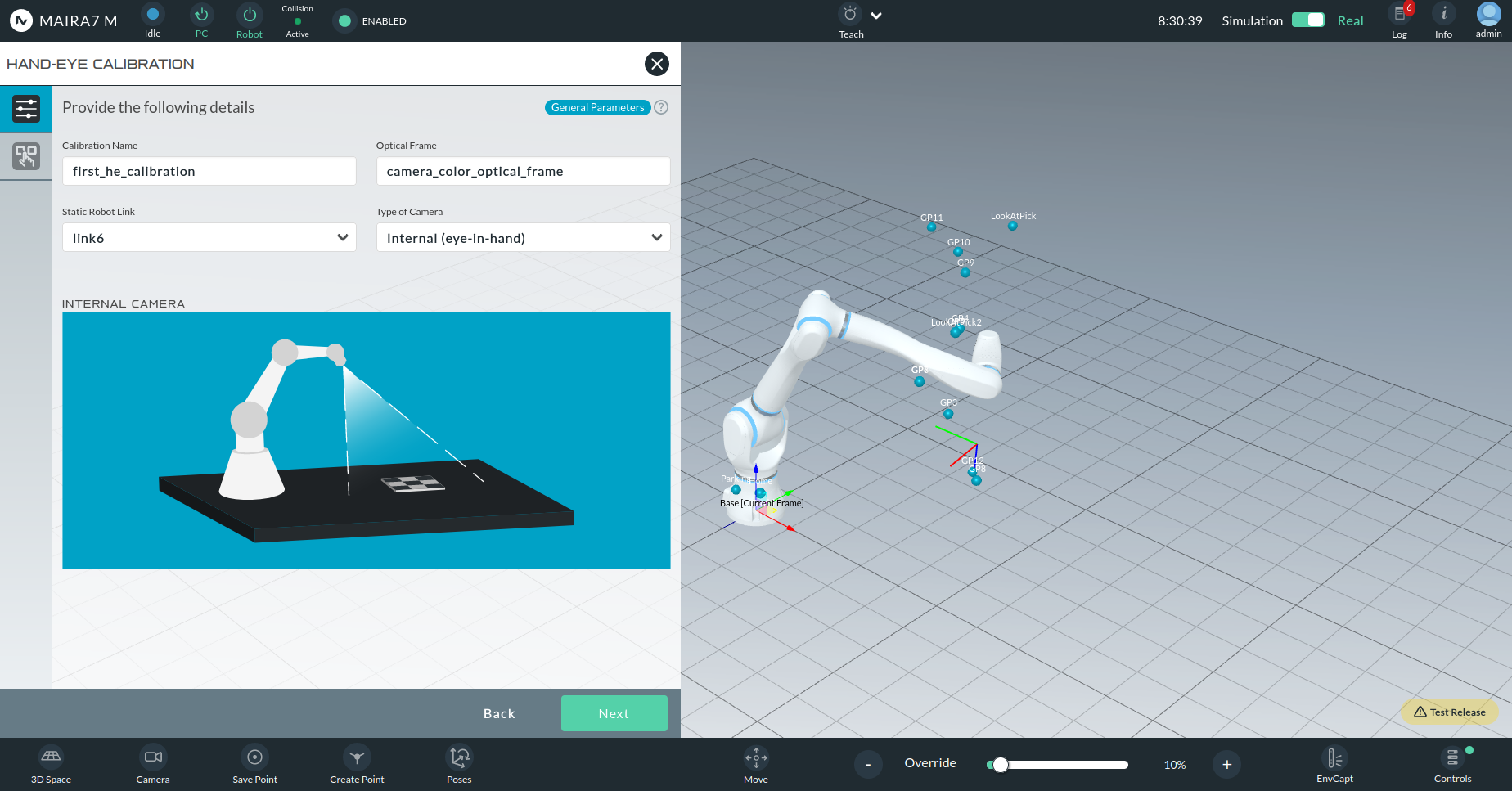
When creating a new calibration, you will be prompted to configure the following:
Calibration Name: Custom name chosen by the user.
Optical Frame: The camera optical frame (e.g., camera_color_optical_frame).
Static Robot Link: The robot link to which the camera or marker is attached.
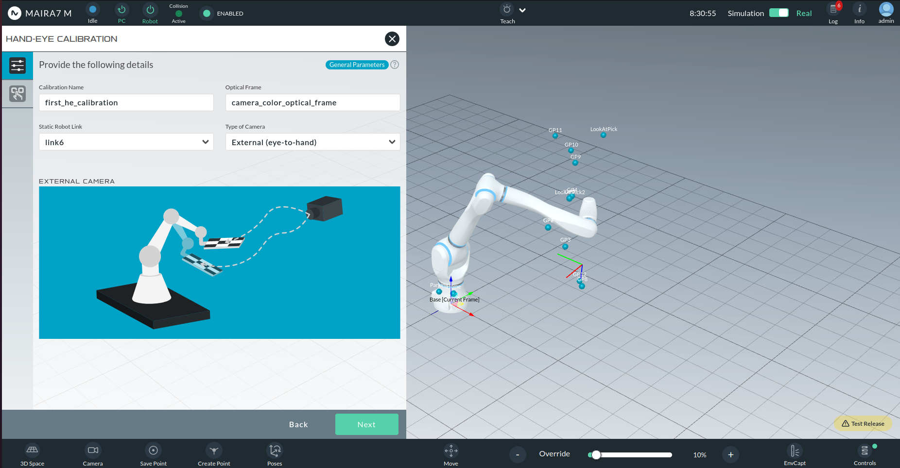
Type of Camera:
Internal (Hand-in-Eye): Camera is attached to a moving robot link.
External (Hand-to-Eye): Camera is fixed in the environment.
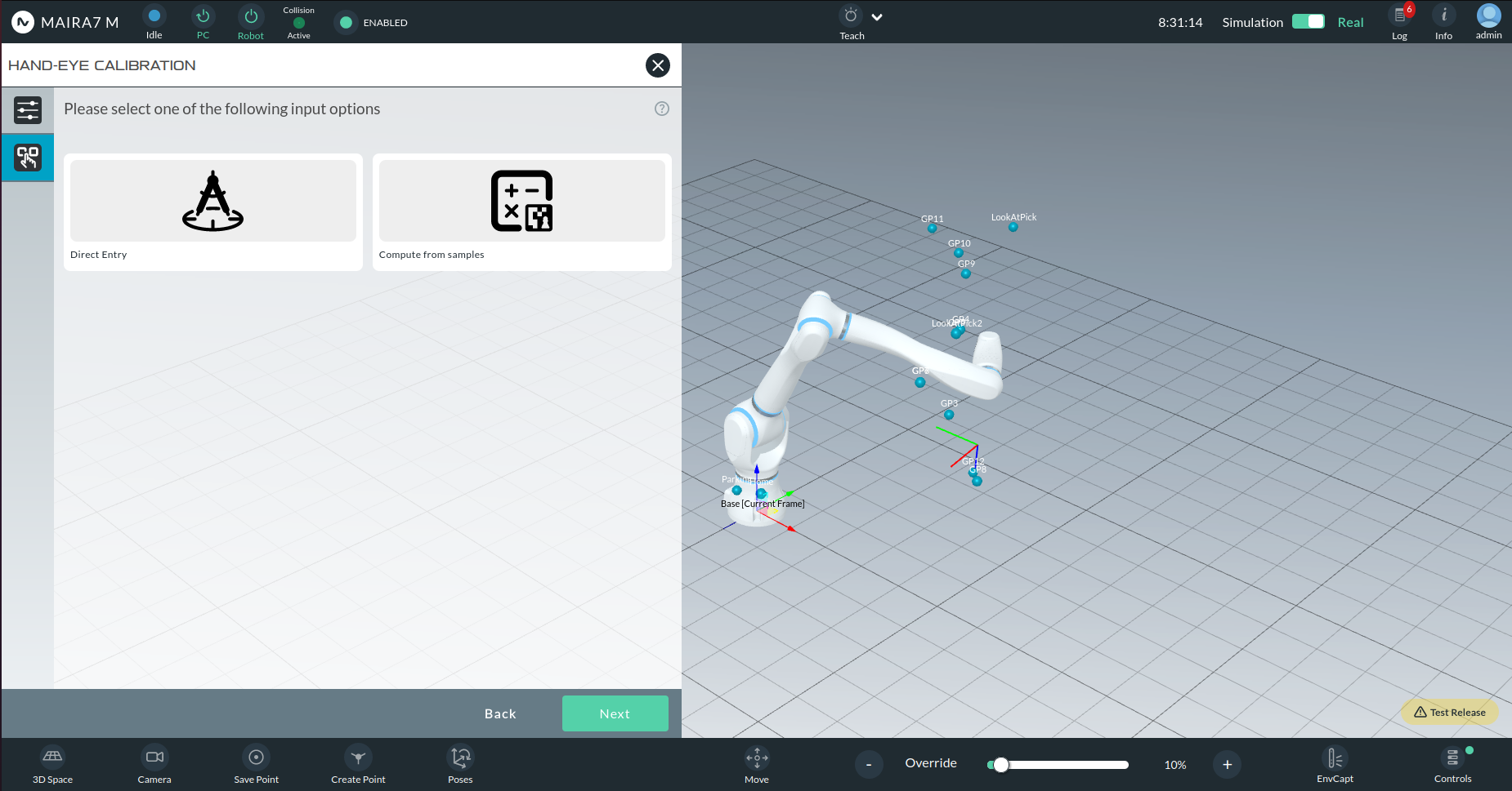
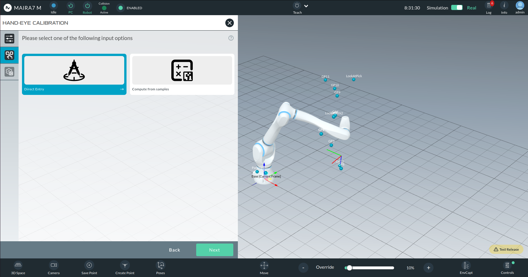
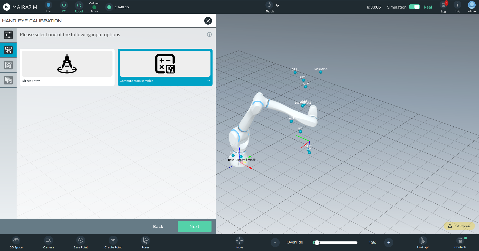
You will then choose between:
Manual Entry: Enter calibration parameters directly.
Compute from Samples: Automatically compute calibration from images.
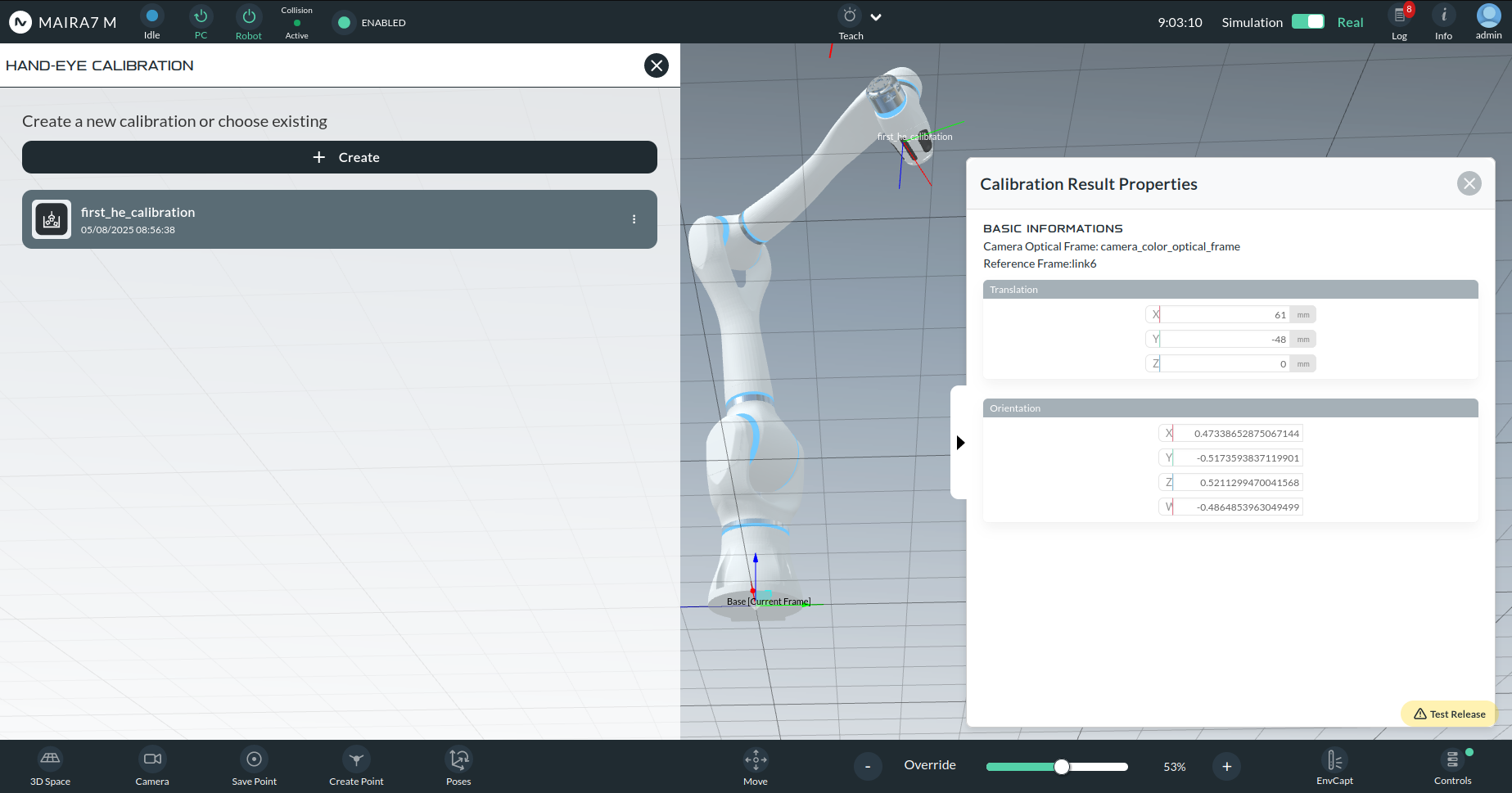
Manual Entry of Calibration Parameters
This option is recommended if you have a backup of a previous calibration and would like to manually input the values.
Required parameters:
Orientation: Quaternions (qx, qy, qz, qw)
Translation: (Tx, Ty, Tz) in millimeters
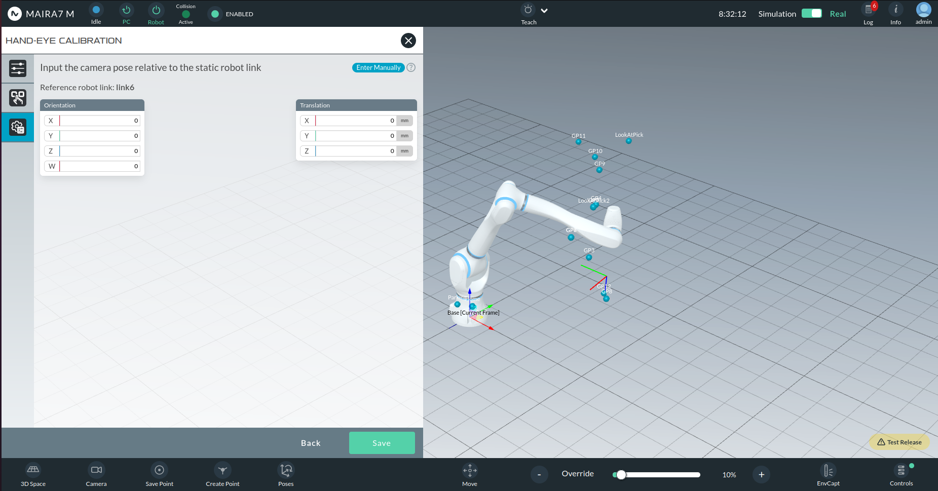
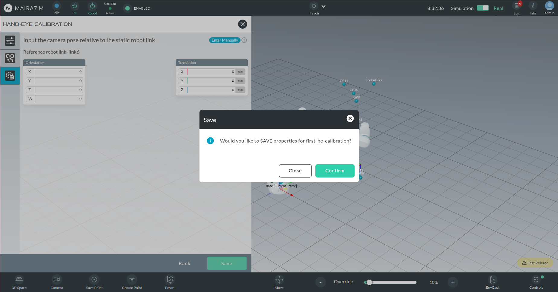
Once values are entered, click Save and confirm.
Computed Hand-Eye Calibration
This option allows you to compute the hand-eye transform from captured image samples of calibration markers taken from multiple viewpoints.
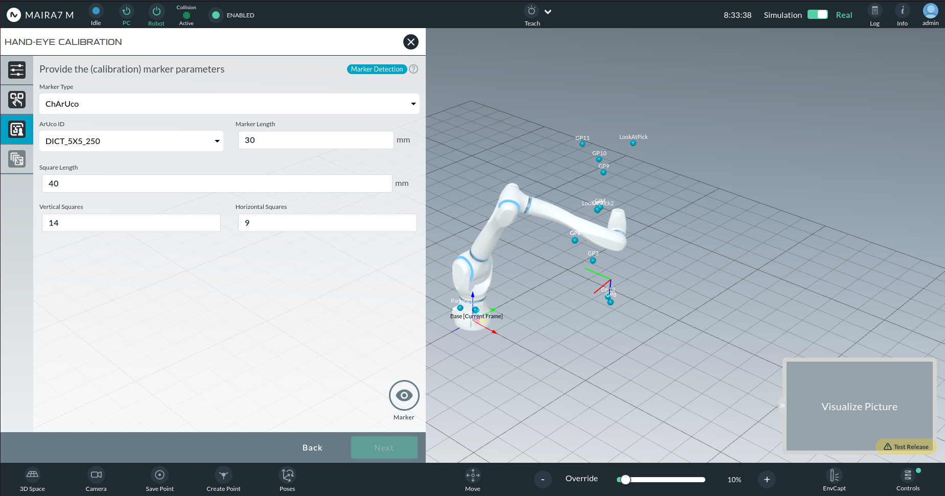
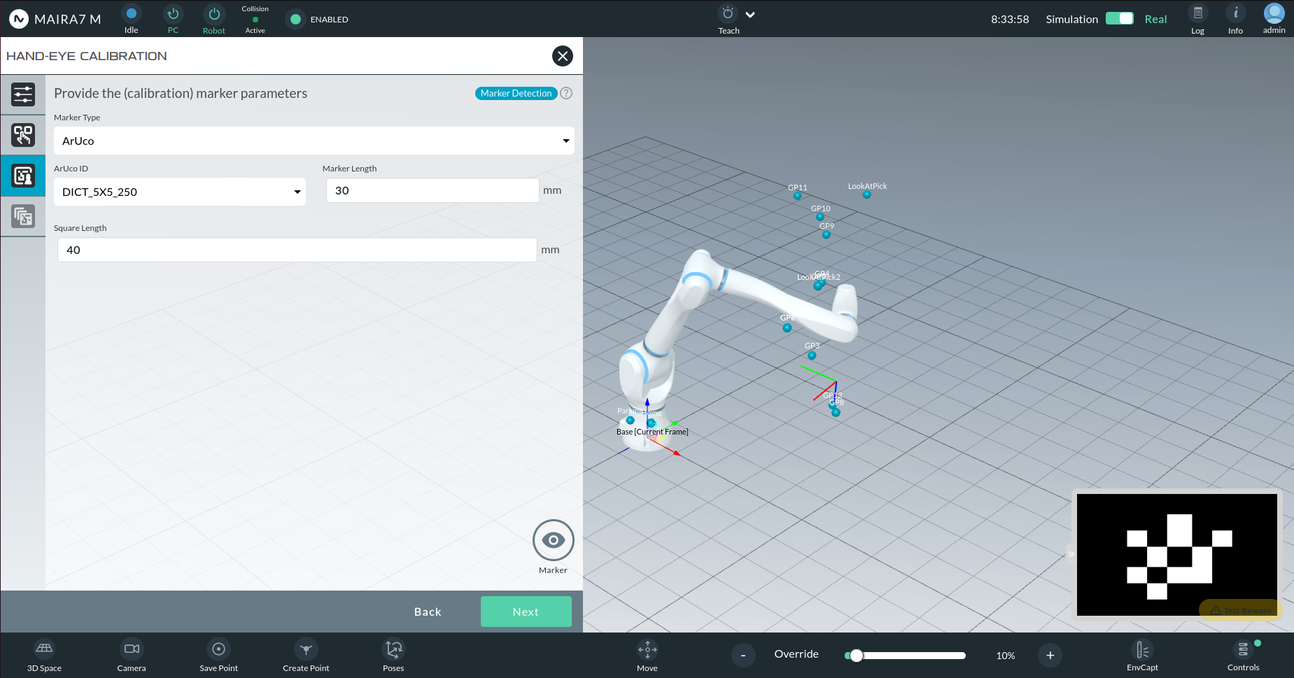
Marker Selection
The wizard supports multiple marker types:
ArUco: Square binary markers with customizable dictionary size (e.g., 4x4, 5x5).
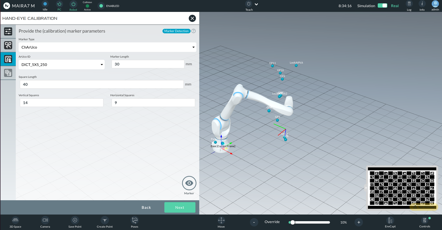
ChArUco: A combination of ArUco markers and a checkerboard grid. Recommended for robustness against partial occlusion.
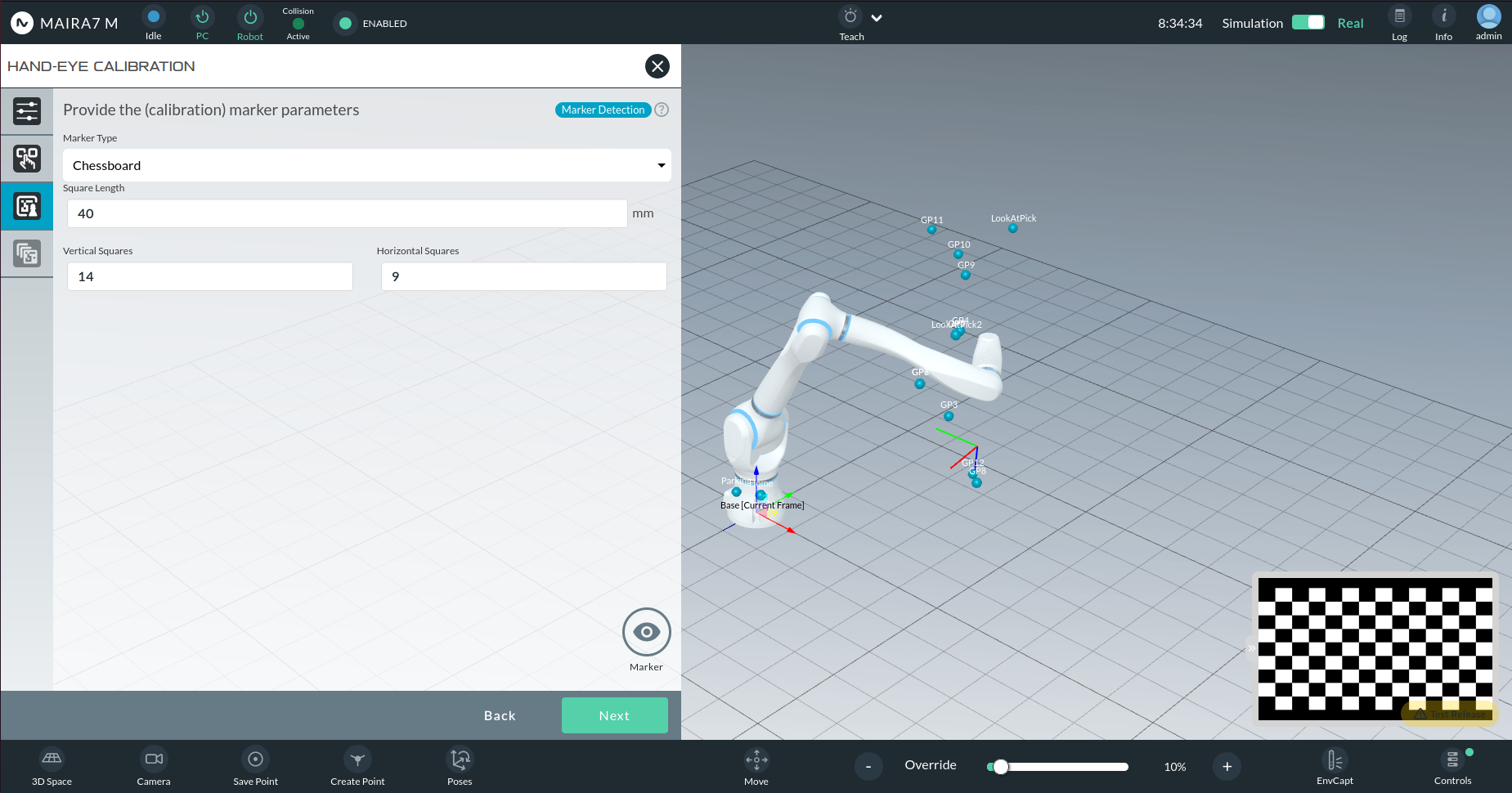
Chessboard: Classic black-and-white grid of squares.
Marker Parameters
ArUco Parameters:
ArUco ID: E.g., 5x5_250 means 5x5 marker, 250 unique IDs.
Marker Length (mm): Size of the black square (excluding border).
Square Length (mm): Size including the white border.
ChArUco Parameters:
ArUco ID: E.g., 5x5_250
Marker Length (mm): Length of the black ArUco marker.
Square Length (mm): Length of white squares around ArUco.
Vertical Squares: Number of squares vertically.
Horizontal Squares: Number of squares horizontally.
Chessboard Parameters:
Square Length (mm): Side length of each square.
Vertical Squares: Number of vertical squares.
Horizontal Squares: Number of horizontal squares.
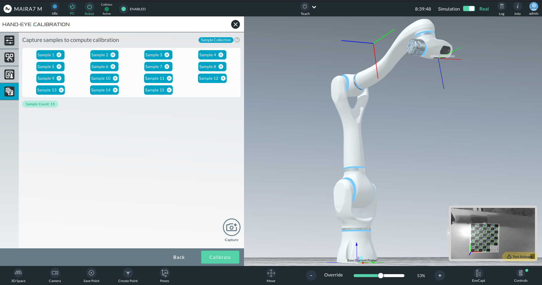
Capturing Image Samples
A live preview of the marker will appear in the bottom-right corner.
Use the Capture button to take an image sample when the marker is visible.
Capture at least 15 samples from different perspectives.
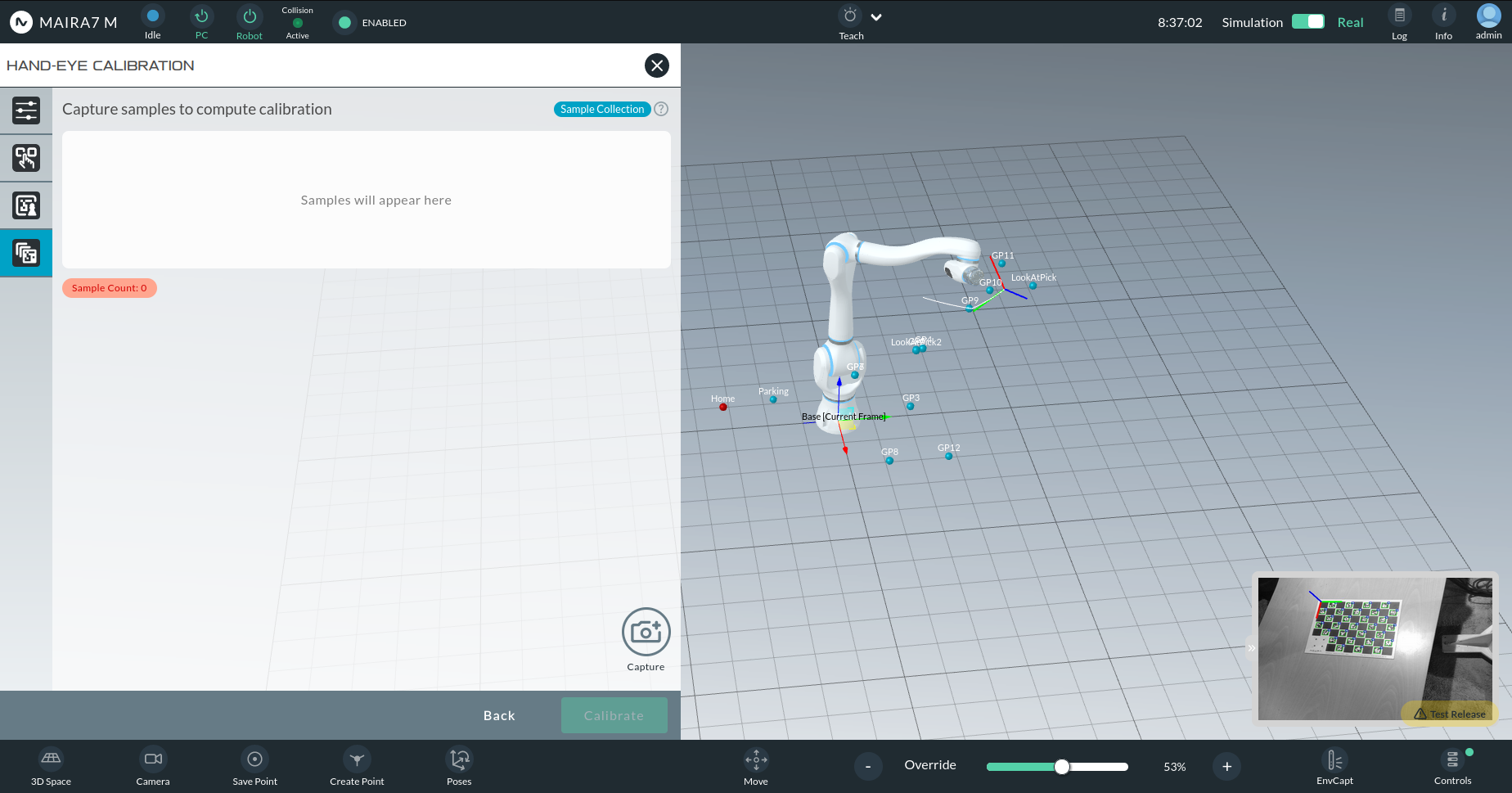
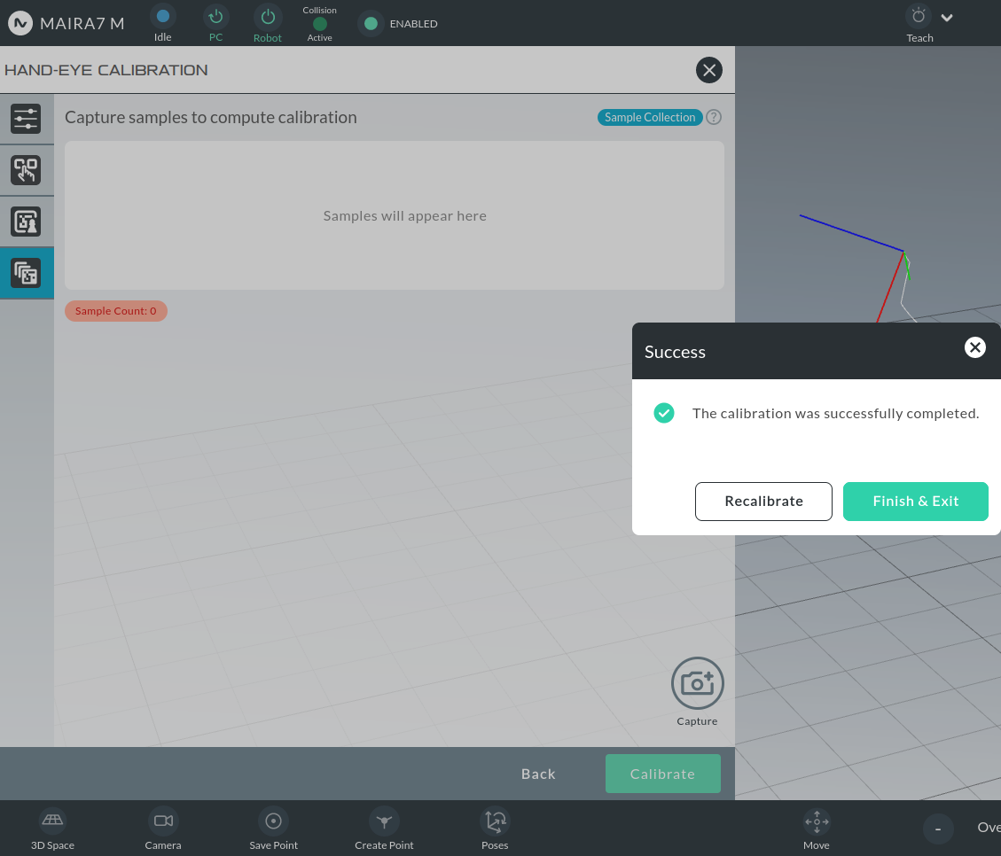
After the minimum number of samples:
An initial calibration result will be visualized in 3D.
If the calibration frame does not align perfectly with the camera optical frame, capture more diverse samples.
Once satisfied, click Calibrate, followed by Finish & Exit.
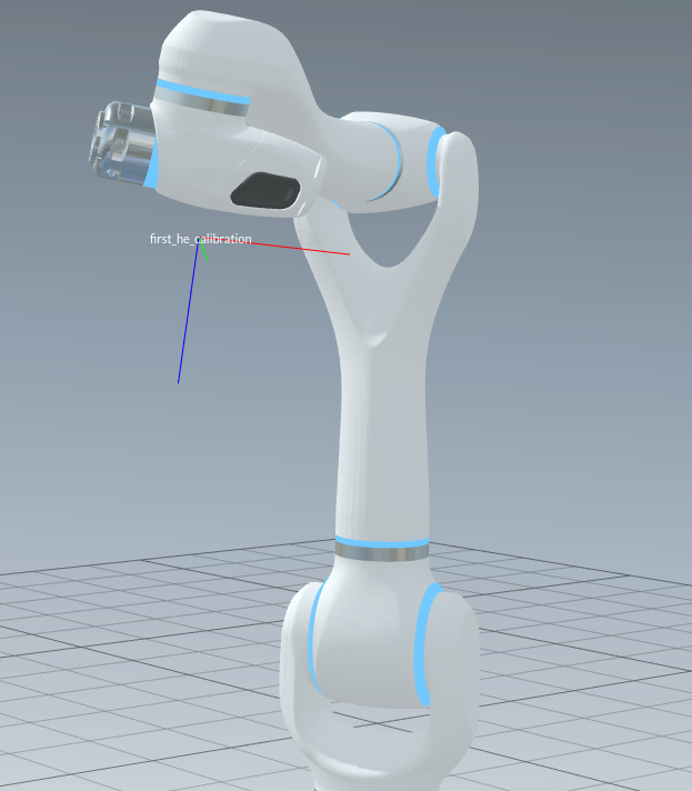
Visualizing the Result
After calibration:
You can view the calibration via the wizard.
A properly aligned Calibration Frame with the camera optical frame indicates a successful hand-eye calibration.
Workspace
The Workspace wizard allows users to define the robot’s operational area by recording a workspace. As most AI functionalities rely on a predefined workspace, it’s essential to complete this step before using related applications.
Check out the tutorials to learn how to create a new workspace or configure an existing.
Grasp Pose Recorder
The Grasp Pose Recorder enables users to record and train preferred grasps for known objects. Please note Objects must be trained for object detection and pose estimation before being used.
This function integrates seamlessly with any pose-aware pick-and-place application on the robot. The recorded grasps will be used in manipulation and data-based pick applications.
See the tutorial on how to enable grasping on a new object.
Apps
Apps offer various AI functionalities that are ready to use on the robot. The following sections offer brief descriptions of these Apps.
Voice Control
The Voice Control system enables users to control the robot using key phrases, eliminating the need for physical interaction with any device. This system comprises two components:
- Voice Activation: to invoke the voice engine by saying “Hey MAiRA”.
If activated, you will hear the feedback sound.
- Voice Commanding: to command the robot after activation by saying e.g.: “Move axis five thirty degrees.”.
Commands are pre-defined and can looked up in the further down.
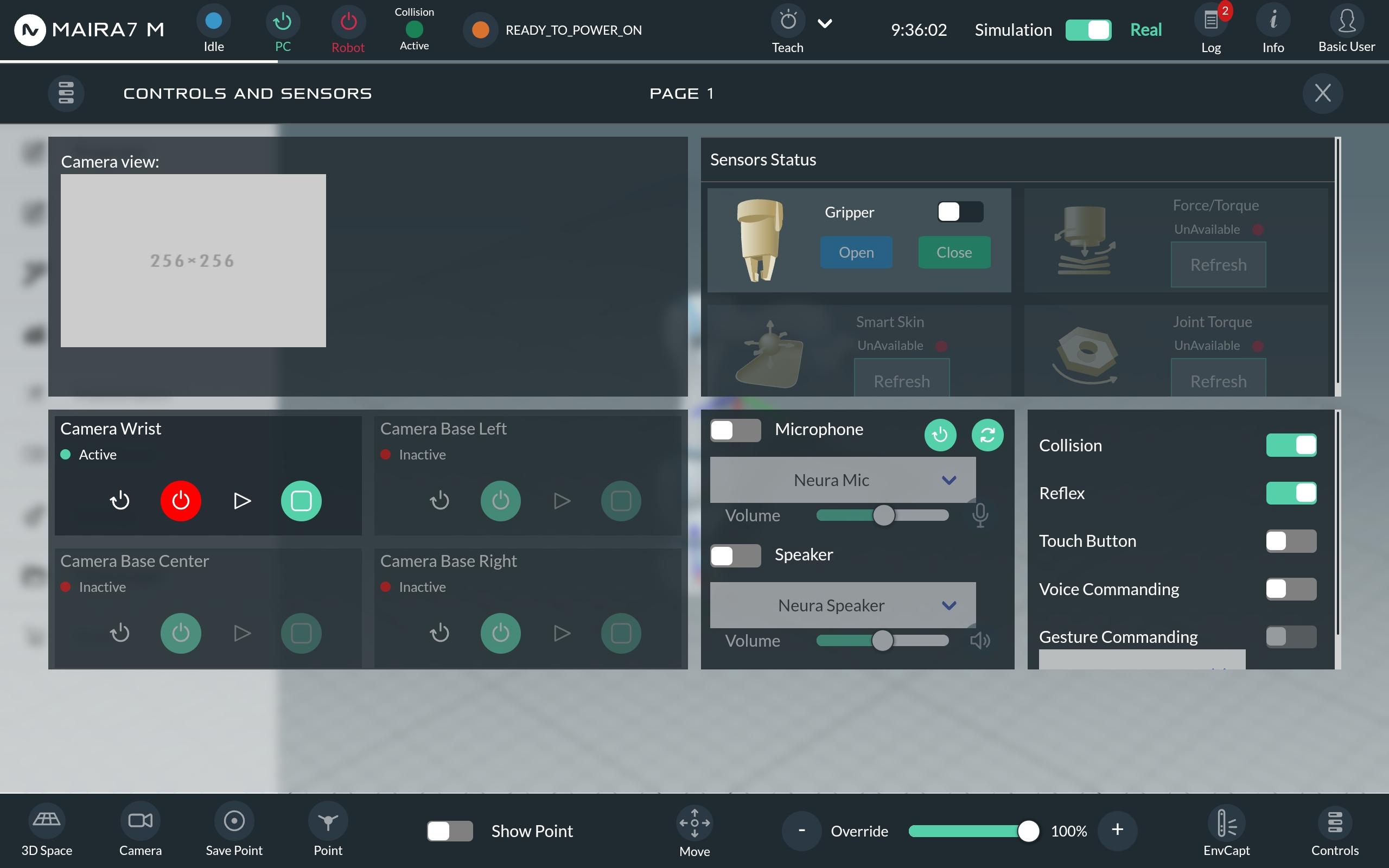
Enabling Voice Commanding
Go to the “Controls” section at the bottom-right-corner (1).
If the “Voice Commanding” toggle button (2) is grayed out (not available), wait for two minutes. This usually happens when the robot is just turned on, and still needs time to check all the available functionalities.
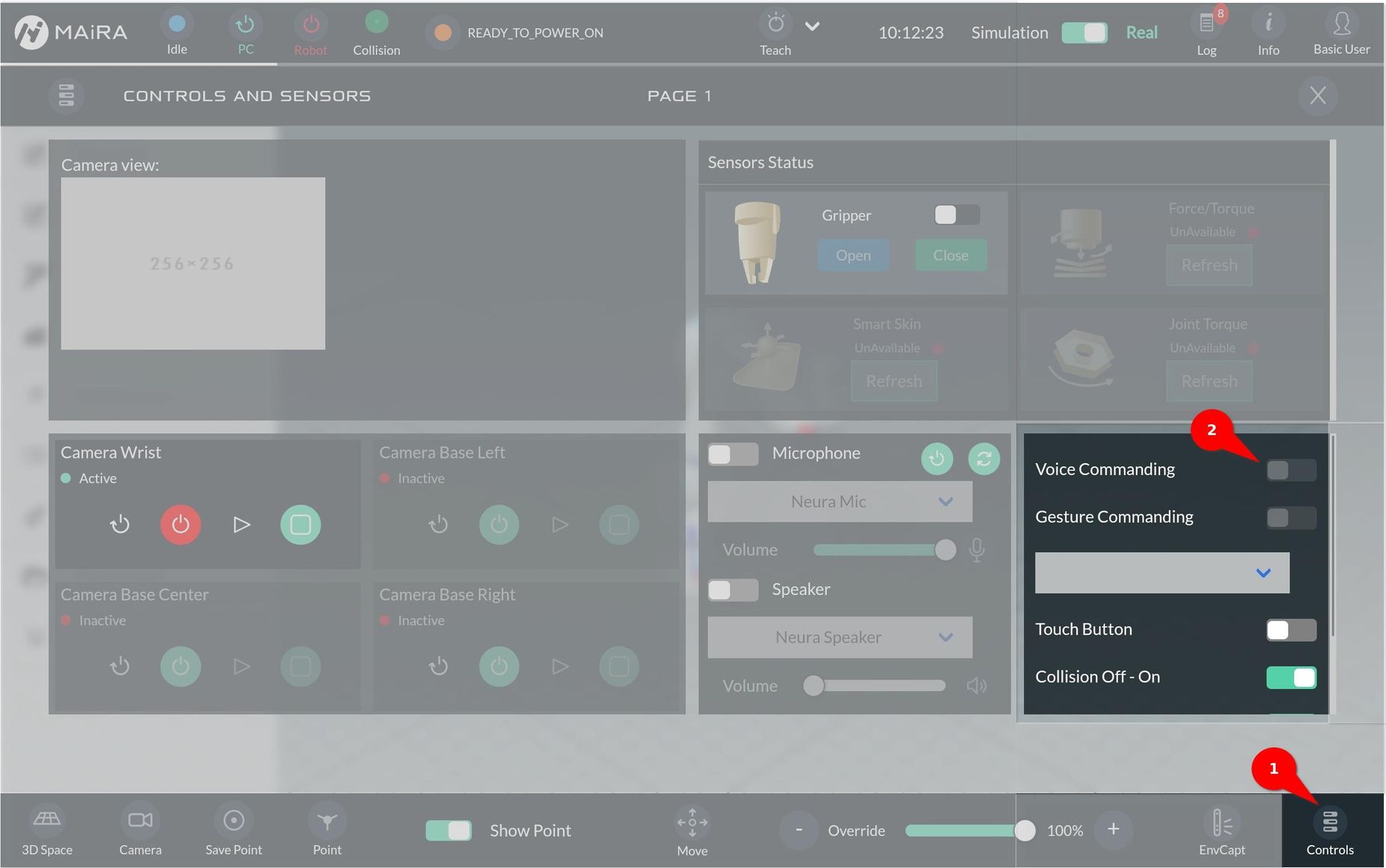
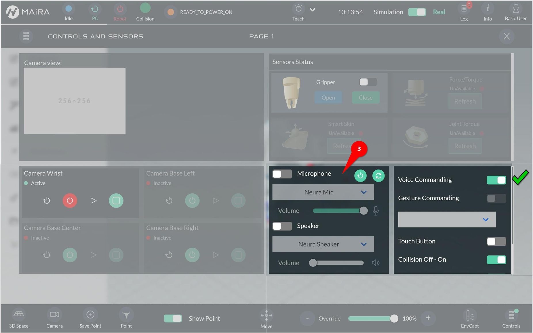
When “Voice Commanding” is ready it can be turned on.
Once activated, you will hear the “Voice Commanding is activated” feedback.
By default, the integrated microphone and speaker are selected.
To select other input/output devices, turn on the toggle button for microphone/speaker (3) and select the appropriate device from the drop-down menu
List of commands
The Voice Control system uses predefined target commands to execute specific actions. The table below lists all available commands (currently 16 commands):
English |
Chinese |
German |
Japanese |
|---|---|---|---|
Move Axis |
移動軸 |
Bewege Achse/Achse bewegen |
軸を移動 |
Move Linear |
線性移動 |
Bewege linear |
ジョイントを移動 |
Move Joint |
移動關節 |
Bewege Gelenk/Gelenk bewegen |
直線移動 |
Free Drive Mode |
無重力模式 |
Freier Bewegungsmodus |
ダイレクトティーチングモード |
Pick |
抓取 |
Griefe ein Objekt |
取ってください |
Open Gripper |
打開抓手 |
Greifer öffnen |
グ リッパーを開いて |
Close Gripper |
關閉抓手 |
Greifer schließen |
グ リッパーを閉じて |
Tic-Tac-Toe |
井字遊戲 |
Tic-Tac-Toe |
三目並べで遊びましょう |
Scan |
掃描 |
Scannen |
スキャン |
Play Trajectory |
重複上一個動作 |
Gebe Bewegungsaufnahme wieder |
動作を再生 |
Record Action |
紀錄動作 |
Aktion aufnehmen |
動作を保存 |
Change Language |
切換語言 |
Sprache ändern |
言語を変更する |
Did you eat? |
你吃了嗎? |
Hast du gegessen? |
ご飯食べました? |
How are you? |
你好嗎? |
Wie geht es dir? |
お元気ですか? |
MAiRA meaning |
麥拉的含意 |
Was bedeutet Maira? |
マイラとは |
I love you |
我喜歡你 |
Ich liebe dich |
好きです |
Tell a joke |
講個笑話 |
Erzähle einen Witz |
冗談を言う |
Staged Commands
All the commands listed in the table above are considered as staged commands. Staged commands require users to follow the robot’s voice prompts to enter the necessary parameters step-by-step.
Example: Hey MAiRA → Move joint → Point one
Example: Hey MAiRA → Pick → One object
Chained Commands
Chained commands allow users to give the full command in one sentence, including any required parameters. Therefore, users can use one sentence to directly make a complete command.
Example: Hey MAiRA → Move axis one by thirty-five degree.
Example: Hey MAiRA → Pick one object.
Safety Feature: Double Check Operation
To avoid accidental actions, Double Check Operation (DCO) in the robot repeats your command to confirm it before execution.
After each command you will hear the feedback voice: “Do you mean …” .
Users need to response with “yes/no”.
Yes: To proceed to the next operation. e.g.: inputting further parameters or executing the command.
No: To go back and correct the previous step.
Double Check Operation is especially important for safety when the robot is moving.
Settings
To change the robot’s language or adjust the language model, go to the AI Settings section.
ScanApp
The Scan App uses the robot’s 3D camera and GPU to quickly scan its surroundings and create a digital 3D mesh. This reconstructed 3D mesh can be used for:
Tool-path generation
Obstacle avoidance
3D data collection
AR/VR use-cases
If you enable texture mapping, you can view the scanned environment with textures using the capture environment feature.
Scanning Types
Environment: The output of scan is point cloud and mesh without cropping
Workspace: The output point cloud and mesh is cropped to a defined workspace
Camera Pose Types
Robot: Uses the robot’s pre-calibrated hand-eye setup
Configuration
Select Workspace: Choose a pre-recorded workspace.
Motion Points: Define points the robot need to move to scan the environment. The robot moves through the points with or without pause.
Scanning Type: Choose between environment, workspace or object scanning.
Camera Pose Type: Select Marker, Robot or SLAM.
File Name: Enter a name to save the file, where the point cloud and mesh is stored.
Parameters
Environment Mesh Simplification Factor: Defines the percentage of triangles is simplified from original mesh that is applied for environment scanning. If you scan a large environment, please increase this value.Object Mesh Simplification Factor: Defines the percentage of triangles is simplified from original mesh that is applied for object and workspace scanning.Environment Scanning Voxel Size: Specifies the size of truncated signed distance function (tsdf) volume for environment scanning. This value depends on the GPU memory of the robot and how large of the environment that is scanned. Increase the value if you scan large environment.Object Scanning Voxel Size: Specifies the size of truncated signed distance function (tsdf) volume for object and workspace scanning.
Gripper
Open and close the selected gripper.
Parameter
Wait Before: Time in ms to wait before moving the gripper.
Gripper Status: Choose wether the gripper should be opened oder closed.
Wait After: Time in ms to wait after moving the gripper.
Mass: The mass of the gripper in kg.
Center of Gravity, X: Point on x-axis in mm.
Center of Gravity, Y: Point on y-axis in mm.
Center of Gravity, Z: Point on z-axis in mm.
Pick
The Pick App enables the robot to identify, locate, and grasp objects using integrated sensors, vision systems, and configurable logic.
The Bin Pick extension builds upon the standard Pick App by offering enhanced capabilities for handling complex scenarios—such as when objects are densely packed, entangled, or positioned in corners. In such cases, the robot may perform additional actions to separate or isolate objects before executing a successful pick.
Note
Workspace Requirements
Before executing a Bin Pick task, you must record two types of workspaces:
Normal Workspace – Represents the general environment setup.
Bin Workspace – Represents the area where the bin is placed, used for accurate planning and collision avoidance.
Multiple Picks with Single Capture: Execute multiple picks using just one camera measurement capture.
Model Selection: Choose between object detection and pose estimation models within the app settings.
Bin Box Configuration: Configure bin box detection and pose estimation either statically or dynamically via parameterization.
Visualization: View bin pose estimation results directly in the app settings.
Foolproof Object Selection: Select objects to be picked from a list tailored to the chosen object detection model, minimizing errors.
Interactive Object Selection: Use an interactive (finger pointing) method to select detected objects.
Reference Points for Robot Motion: Introduce start and end reference points to append robot motion before and after the pick.
Pick Success Check: Use gripper feedback to determine successful or failed picks.
Result Evaluation: Evaluate pick results based on criteria such as the number of successful picks and completion of picks, supporting IF/ELSE conditions.
User Interface Improvements: Enhanced user interface for a better overall experience.
Pick Types
The Pick App supports the following four main pick types:
General Pick
Pose-Agnostic Pick
Pose-Aware Pick
Marker-based Pick
General Pick
The General Pick method autonomously identifies and selects objects to pick within the workspace using only sensor input. It does not require any prior knowledge, training, or pre-recorded data about the objects. The system generates pick candidates—deciding which objects to pick and how to pick them—purely based on real-time perception. This pick type is ideal for use cases such as object handovers, workspace cleaning, or other tasks where specific object placement or identification is not required.
Pose-Agnostic Pick
The Pose-Agnostic Pick utilizes a pre-trained object detection module to identify and differentiate between various object types in the workspace. The user can specify which object types should be picked. However, no pose estimation is performed, and picks are generated without knowledge of the object’s orientation—hence the term pose-agnostic. This approach is well-suited for applications such as object sorting, where objects of different types need to be picked and placed into separate bins or locations, regardless of their orientation.
Pose-Aware Pick
The Pose-Aware Pick performs grasping actions based on the detected 6D pose of the object, making it pose-aware. The workflow involves two main steps:
Object Detection: The system first identifies specific object types, as selected by the user.
Pose Estimation: A pose estimation module determines the orientation and position of the selected objects. Based on this information, grasp candidates—defined in the object’s coordinate system—are generated either through manual teaching or automatic grasp synthesis.
The pose estimation module can be either:
Deep Learning-based (Pose-Aware DL), or
Non-Deep Learning-based (Pose-Aware nonDL).
This pick type is recommended for applications requiring high precision, such as accurate pick-and-place tasks or situations where the object must be picked from a specific orientation or placed with exact alignment.
Marker-based Pick
Marker-based picking enables the generation of grasp poses relative to a predefined marker placed on the object. The user can specify both translational and rotational offsets from the marker’s detected pose to define the desired grasp pose. This approach ensures precise and consistent pick operations based on the marker’s location and orientation.
Pick within Bin Box
All three pick types—Pose-Agnostic Pick, Pose-Aware Pick, and Marker-Based Pick—can be executed either in a standard workspace (e.g., a flat table) or within a bin box environment. When operating within a bin box, it is essential that the pose of the bin box is known to ensure safe and collision-free motion planning. In the Pick App, the bin box pose can be:
Statically configured via the graphical user interface (GUI), or
Dynamically detected using the integrated bin detection module.
This flexibility enables safe and efficient picking in both structured and semi-structured environments.
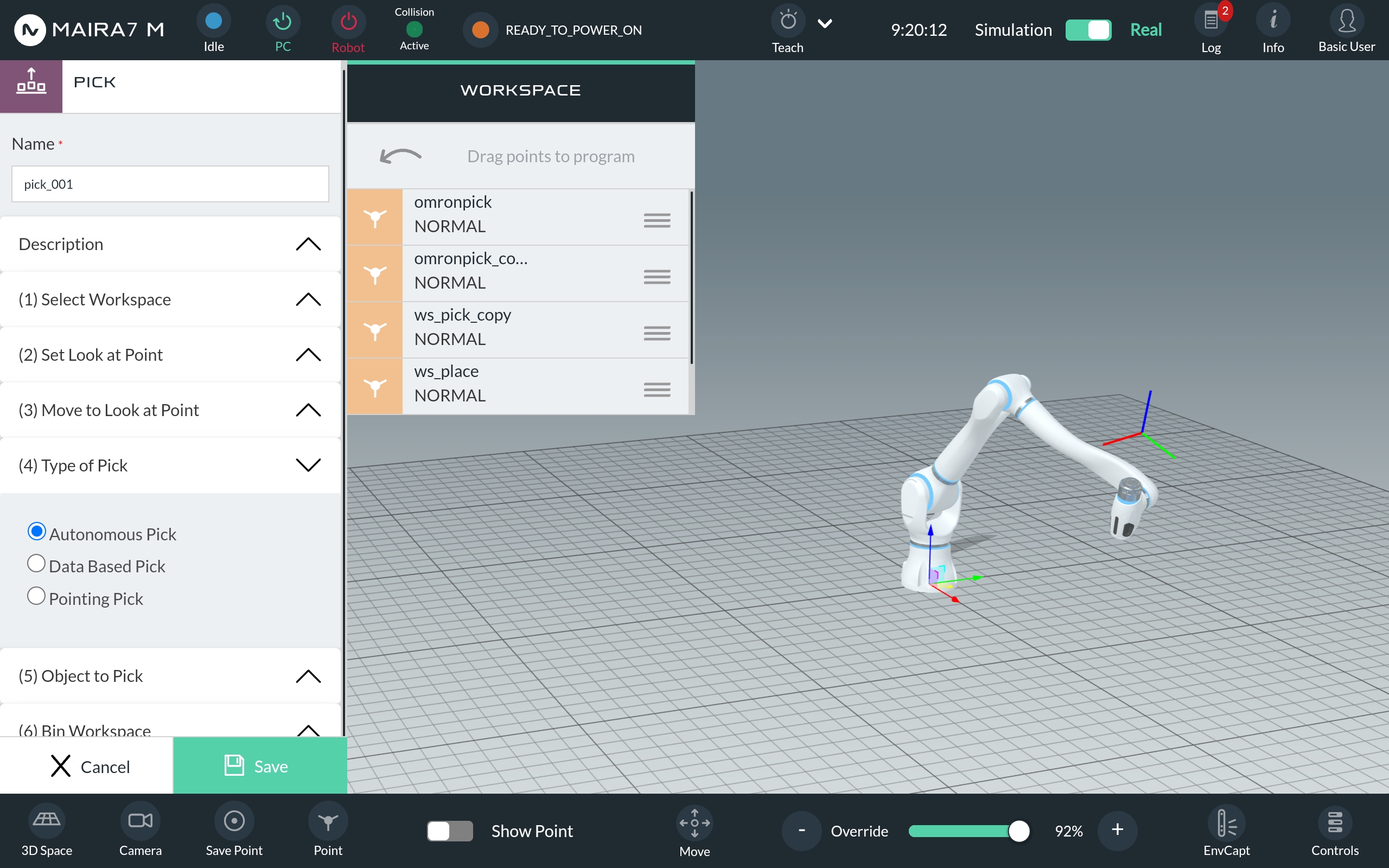
Configuration
General Configuration
This section defines the key settings for project setup, workspace selection, object picking, and motion planning.
Information:Set the name and description of the project.
Workspace: Load a pre-recorded workspace as region of interest.
Look at Points: Select multiple points as look-at points. These points are used to scan the workspace and objects.
Start Reference Point: Set reference point for start of the picking process.
End Reference Point: Set reference point for end of the picking process.
Bin Workspace: Select a pre-recorded bin workspace.
Bin Pose: Enable or disable bin detection during picking.
Method: Choose between using a bin model for localization or relying on a pre-configured bin workspace.
Bin Model: Load a bin model
Bin Pose Estimation Perios: Adjust the frequency of the bin detection
Cropping Factor: Define the percentage of the bin height, which is used for bin detection. Value can affect the speed of detection.
Pick Type: Choose the Pick Type - general, pose-agnostic, pose-aware(DL) or pose-aware(Non-DL).
Objects: Specify the object to be picked.
Touch in Image: Uses bin detection method uses the bin model to localize the bin, without bin detection methods needs to hav a bin workspace set up.
Select from a List: Load a bin model
Point to Object: Select and modify the frequency of the bin detection
Motion PLanning: Set motion planning parameters.
joint speed: Speed of Move Joint.joint acceleration: Acceleration of Move Joint. Should match the joint speed, otherwise the robot may shake.linear speed: Speed of Move Linear.linear acceleration: Acceleration of Move Linear. Should match the joint speed, otherwise the robot may shake.
Advanced Parameters
These settings allow fine-tuning of collision detection, grasp planning, and object handling.
collision_pcd: Enable collision check between end effector and point cloud captured from the sensor.collision_workspace: Enable collision check between end effector and workspace.is_suction_gripper: Turn on, if a suction gripper is used.general_grasp_detection_method: Not implemented yet.pre_grasp_distance: Distance from pre-grasp pose to grasp pose along the z axis(approach axis) of the end effector.post_grasp_distance: Distance from post-grasp pose to grasp pose along the z axis of the robot (intuitively speaking toward up).max_grasp_candidates_per_instance: Maximum number of generated grasp candidates for each object instance.max_pick_attempts_per_capture: Maximum number of pick attempts after one single capture of camera measurement.threshold_radius: Angle threshold for random pick. Only picks that have an angle to approach direction within the range of this threshold will be returned.general_grasp_offset_x: Additional x offset for pick in end effector coordinate. This will ignore the collision checking. Please use carefully.general_grasp_offset_y: Additional y offset for pick in end effector coordinate. This will ignore the collision checking. Please use carefully.general_grasp_offset_z: Additional z offset for pick in end effector coordinate. This will ignore the collision checking. Please use carefully.collision_space_padding: Padding of the collision space.general_place_offset: Vertical offset distance between position of placing object and surface.default_opening: Distance between two fingers when the end effector is approaching the object.approach_direction: Desired approach direction w.r.t the workspace.compare_ranking_method: Method used to rank the picks. Available options are:joint_state: Ranks candidates according to the joint-wise distance from pick candidate to the reference joint state. Default joint state is the current joint state (the moment when you select this option for the first time).orientation: Ranks the candidates according to the orientation of the approach direction. The closer the pick is to the desired approach direction, the better.height: Ranks the candidates according to the height of the pick along the approach direction. The higher the better.quality: Ranks the candidates according to the quality of the pick. The higher the better.
Place v2
Place v2 application allows the robot to place grasped objects at specific locations within the workspace. It supports three different placement methods, giving flexibility based on your needs: Three place types are supported:
Point selection
Drag and drop pre-defined points from the list. Choose one point in “Single Point” modus or multiple points in “Multiple Points” modus.
Gesture
Show the robot where to place the object by pointing with your right hand. This place type is only available in “Single Points” modus.
Grid Based Points
Multiple placing points are defined by using a grid. The can be configured by several parameters (see below). This place type is only available in “Multiple Points” modus.
Note
To use the PlaceV2 App in a program, ensure that a Pick App is executed first. Then, use an If logic check to confirm that the pick was successfully completed. If the pick was successful, the PlaceV2 can be executed.
Configuration
General Configuration
These settings help you define how the system behvaes within your workspace.
Information: Enter the name and description of the project.
Workspace: Choose a pre-recorded workspace as your region of interest.
Look at Points: Select multiple points the system should focus on while scanning the workspace and objects.
Bin Workspace: Select a pre-recorded bin workspace.
Bin Pose: Enable or disable bin detection during picking.
Method:
With bin detection method: Uses object detection to identify the region of interest to localize the bin pose
Without bin detection: Uses the given workspace as region of interest to localize the bin pose.
Bin Model: Load a bin model if requied.
Bin Pose Estimation Period: Modify the frequency of the bin detection.
Cropping Factor: Set the percentage of the bin height, used for bin detection. Adjusting this value can affect the speed of detection.
Place Type: Select the method for point selection, gesture or grid based points.
Motion PLanning: Adjust motion planning parameter.
joint speed: The speed for Move Joint operations.joint acceleration: The acceleration for Move Joint. This should match the joint speed to avoid shaking.linear speed:The speed for Move Linear operations.linear acceleration: The acceleration for Move Linear. This should match the joint speed, otherwise the robot may shake.
Grid Parameters
These settings help you define the grid layout and how objects will be placed in the grid:
origin: Drag and drop a saved point to set the origin of the grid.offset[x,y,z]: If bin localization is enabled, set the offset in mm between the bin origin and the grid origin.cell count: Define the number of grid cells in the x, y, and z directions starting from the grid origin.cell size: Set the distance between two adjacent grid points in the x, y, and z directions.sequence: Choose the order in which the grid points are processed. Available options are: [xy, xz, yx, yz, zx, zy].
Advanced Parameters
These advanced parameters allow you to fine-tune the placement of objects. Here’s an explanation of each parameter:
pre_place_distance: This parameter defines the distance (in mm) for the robot to move linearly before reaching the place pose. It helps position the robot in the right place before placing the object.post_place_distance: This parameter sets the distance (in mm) for the robot to move away from the place pose after placing the object.object_orientation: Controls the orientation of the object when placing it at the desired location. -pick_orientation: The object will be placed with the same orientation it was grasped in. -workspace_orientation: The object will be aligned according to the orientation set in the workspace.place_offset_z: This parameter applies an offset in the direction of the tcp for generated place pose (in mm).
Positive values will raise the placement position.
Negative values will lower the placement position.
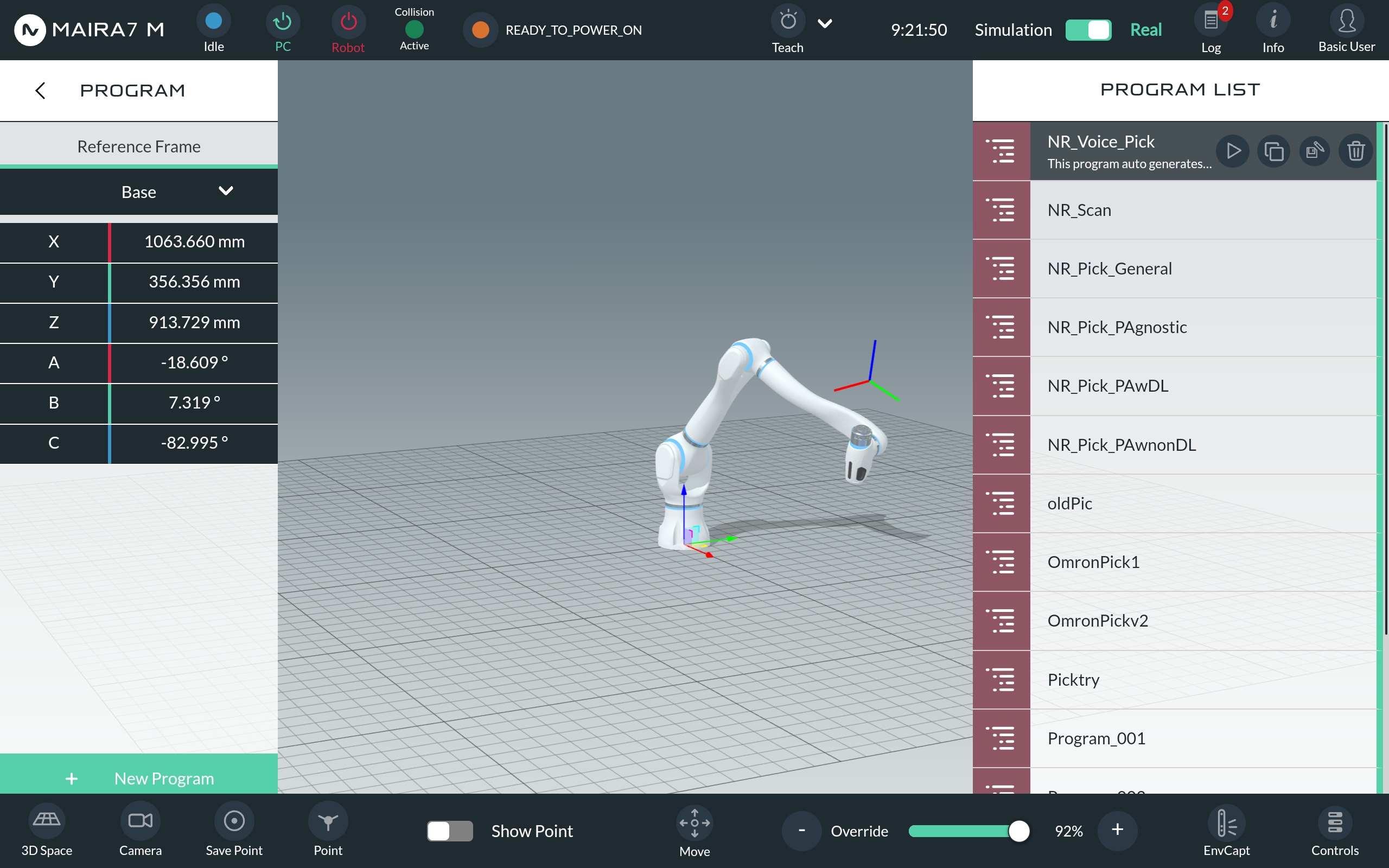
Demo Programs
Neura provides several ready-to-use programs that demonstrate the functionalities of the AI Apps in specific scenarios These programs are available under HOME > PROGRAM.Below is a brief overview of each program:
Program Name |
Description |
|---|---|
Use your voice to communicate with MAiRA and tell her which object to pick. |
|
Scan the environment and objects in the workspace. |
|
NR_Pick_General |
Pick objects in the workspace using a general picking method. |
NR_Pick_PAgnostic |
Pick objects using a pose-agnostic picking method. |
NR_Pick_PAwDL |
Pick objects using a pose-aware deep learning-based picking method. |
NR_Pick_PAwnonDL |
Pick objects using a pose-aware, non-deep learning-based picking method. |
To start a program, click on the desired program from the list and press the Play button. You can also duplicate a program (using the Copy button) or edit/save it (using the Edit/Save button).
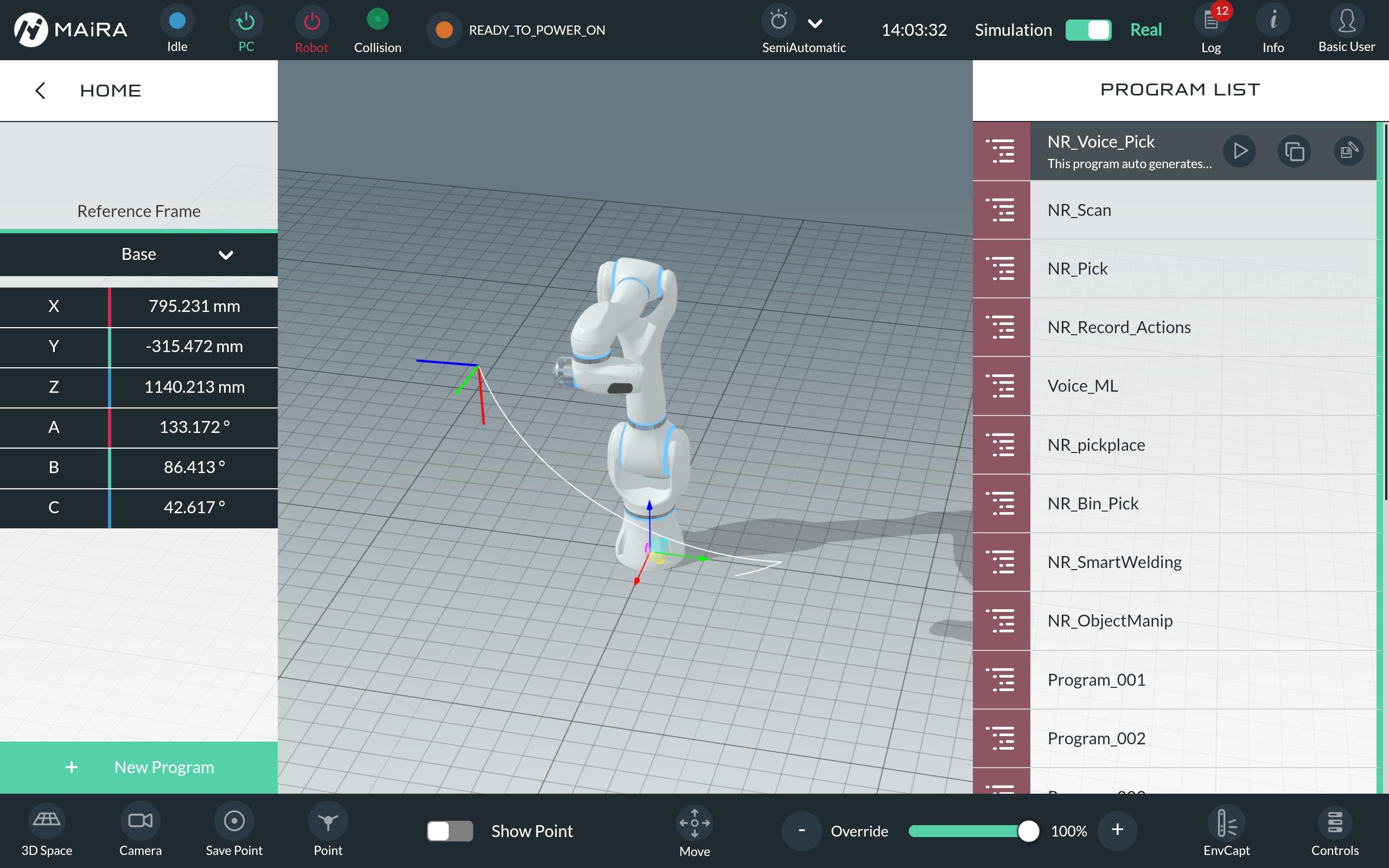
See the create custom programs page to get more information on editing programs. The programs are mainly build using the AI Apps.
Voice Pick
This program demonstrates MAiRA’s ability to listen to voice commands, recognize pre-trained objects, and generate a grasping pose for known and unknown objects.
Preparation
Define a workspace (workspace tutorial).
Place objects in the workspace.
Make sure voice commanding is enabled(sensor settings).
Ensure the camera is activated (sensor settings).
Verify the correct object segmentation model is loaded,(object detection settings).
Activate the voice commanind by saying “Hey, MAiRA”.
Instruct MAiRA to pick a specific object, “pick mouse” or non specific “pick any object”. Make sure the right AI model is chosen in the AI settings.
MAiRA will repeat the command before executing. Confirm with “yes” or decline with “”no”.
MAiRA will generate a grasping pose (displayed on the GUI) and proceed to pick the object.
Scan
The Scan program demonstrates how to scan the workspace using the Scan App. For more information and configurations, navigate to the Scan App.
Preparation
Define a workspace (workspace tutorial).
Place the object to scan inside the workspace.
Ensure the camera is activated (sensor settings).
Pick
This program allows MAiRA to recognize and grasp objects in the workspace one after the other, using a specific pick type. See the explanation of the pick types here.
Preparation
Define a workspace (workspace tutorial).
Place objects inside the workspace.
Ensure the camera is activated (sensor settings).
Verify, if the right object segmentation model is loaded (object detection settings).
Create a Custom Program
Neura provides a drag-and-drop interface for creating customized programs, combining basic motions, logics, and AI Apps. These programs can be executed directly by the robot. Below is a list of available items you can use in the program:
Motions |
Logics |
Apps |
|---|---|---|
MoveJoint |
ProgrammImport |
ScanApp |
MoveLinear |
Wait |
Gripper |
MoveCircular |
Loop |
TareFTS |
MoveComposite |
If |
PalletToPallet |
MoveRecordedPath |
ElseIf |
MachineTending |
MoveExternalAxis |
Else |
Palletizing |
MoveServo |
SetVariableValue |
EasyTeach |
MoveRelative |
ExternalDevice |
|
PlaceV2 |
||
Pick |
For more detailed desription of the AI related Apps can be found here.
Note
Some Apps require a defined workspace. Check out this page, to get more information about workspaces!
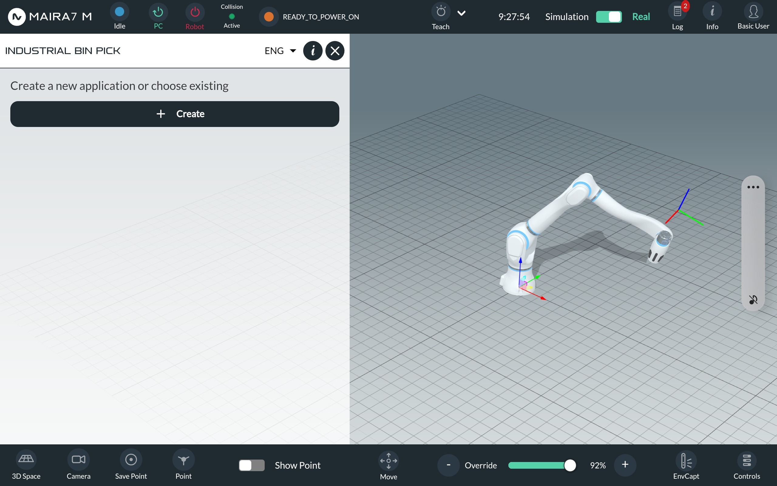
To create a custom program, navigate to HOME > PROGRAMS and click on the “+ New Program” button on the bottom left corner.
Click on “+ Create” to begin building your program.
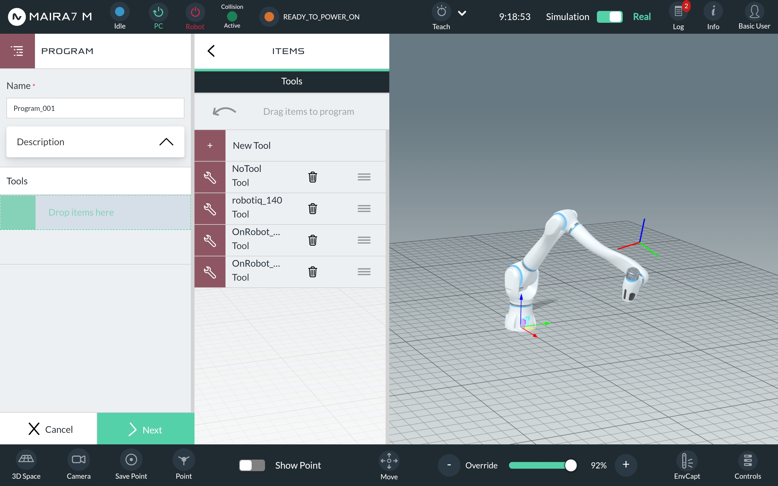
Name your application and provide a description. Select the tools you want to use by dragging and dropping them from the list of available motions, logics, and Apps.
Add motions, logics, or Apps by dragging them to the program setup area. To edit or delete an item, simply click on it.
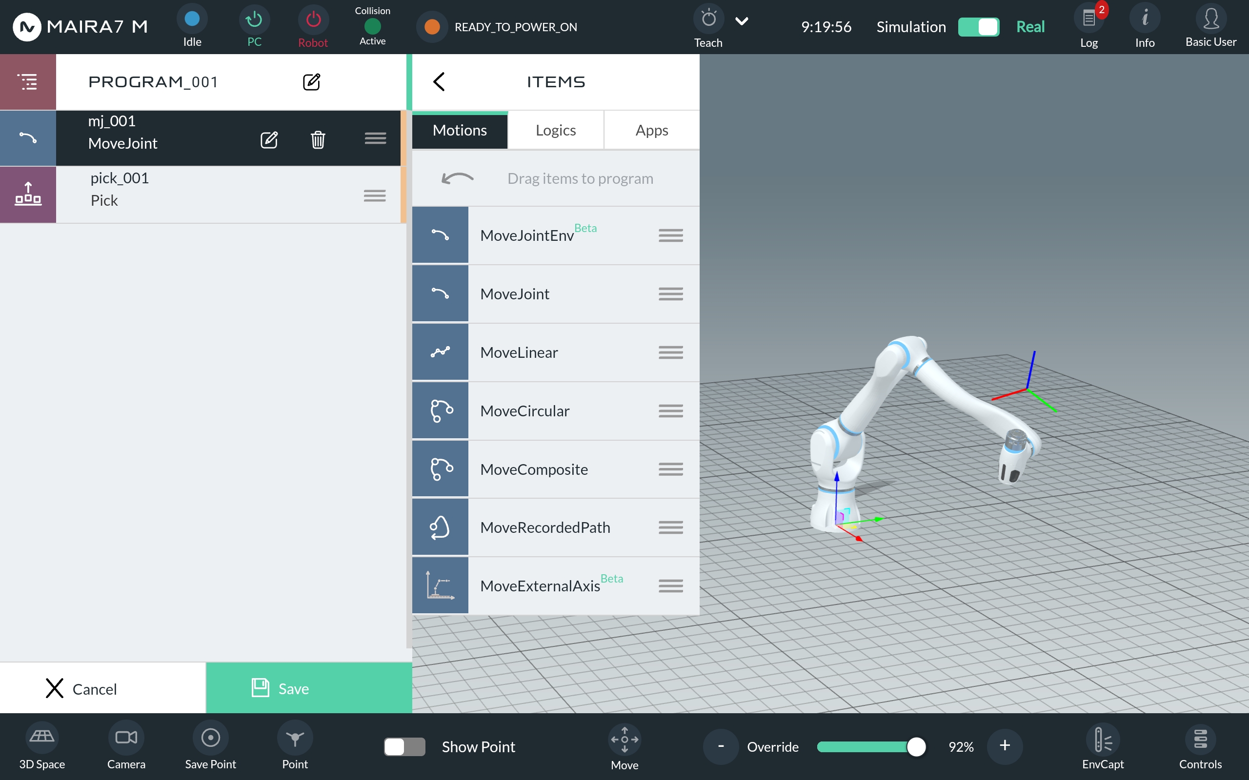
To finish and save the program, click the green “Save” button.
AI Settings
This section explains how to configure AI functionalities of the robot.
Settings regarding AI functionalities can be set by navigation to HOME > SETTINGS > AI.
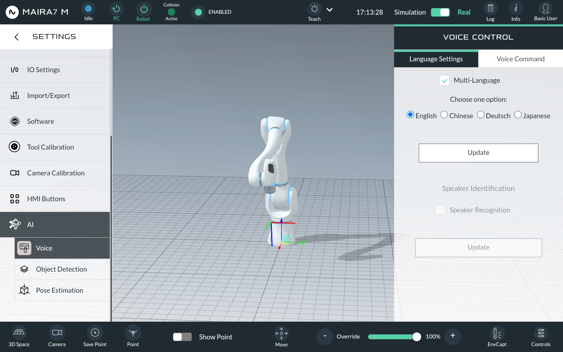
Voice
Customize the robot’s voice and language preferences.
Language Settings:In Language Settings change the language of the robot (currently supported languages: German, English, Chinese and Japanese).
Voice Command:In Voice Command update the language model and change the sensitivity of the voice activation.
Important
After making any changes, be sure to click the Update button after choosing an option to save your settings. Changes will not be applied if you don’t update!
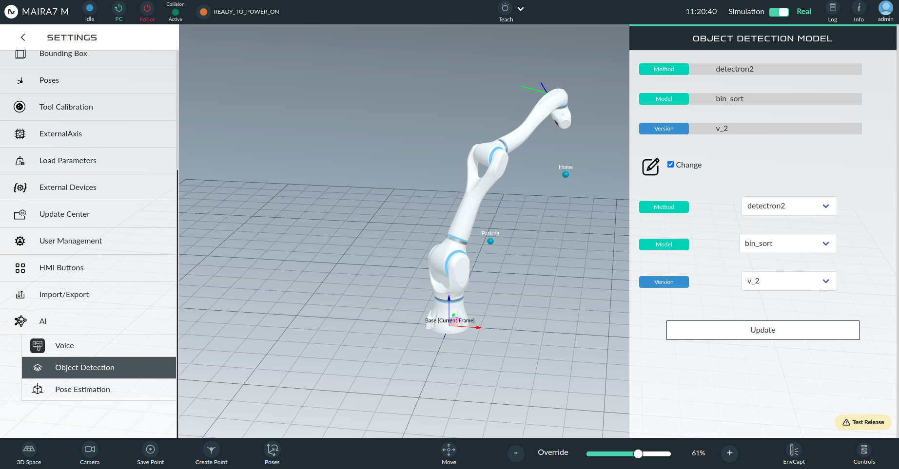
Object Detection
Manage the object detection feature by uploading pretrained models and selecting segmentation methods. Currently three deep learning-based methods (neura_DLIS1, neura_DLIS2 and neura_DLIS3) are supported.
To change the currently selected options, mark the Change field. After selecting the desired method, model and version of the model, click Update to save the changes.
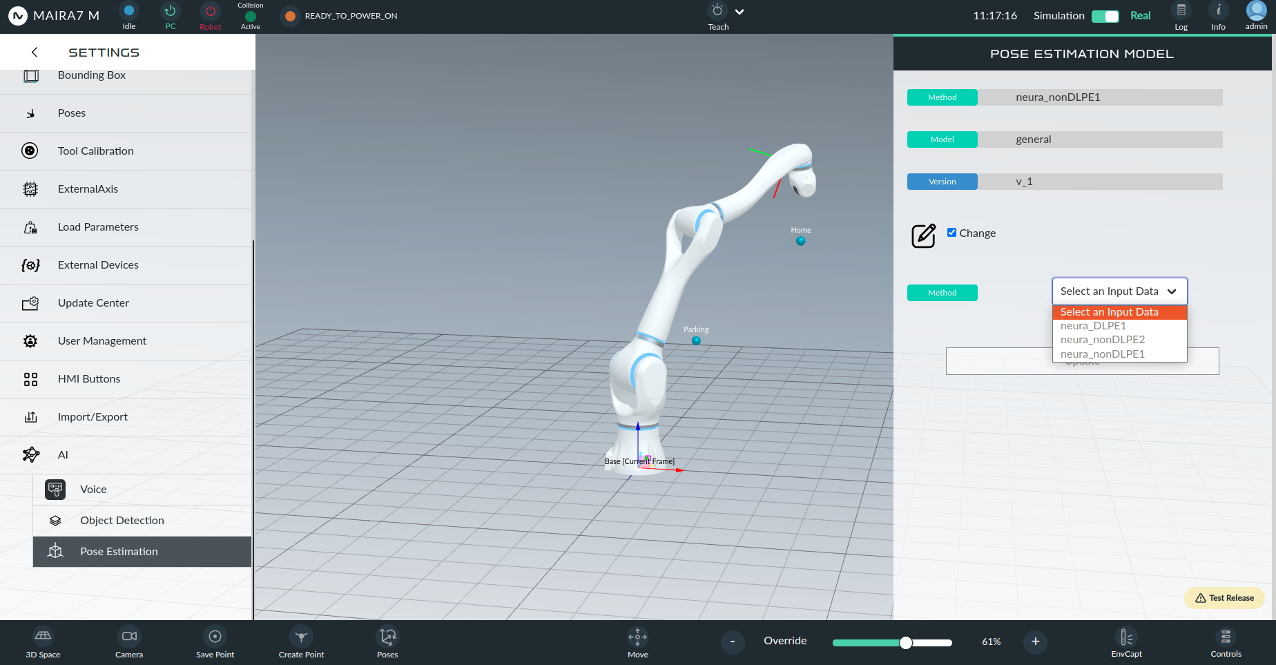
Pose Estimation
Configure pose estimation of objects with supported models.
Upload a pretrained model for object pose estimation of objects and select the desired pose estimation method. Currently, two non-deep learning-based methods (neura_nonDLPE1 and neura_nonDLPE2) and one-deep learning-based method (neura_DLPE1) are supported.
To change the currently selected options, mark the Change field. After selecting the method, model and version of the model, click Update to save the changes.
Sensors
To check and control the sensors, navigate to “Controls” located at the bottom left of the screen.
- In this section, you can control the following sensors:
Camera: Currently, MAiRA only has a wrist-mounted camera. Turn the camera on/off.
Microphone: Select the hardware, control the volume and turn the microphone on and off.
Speaker: Select the hardware, control the volume and turn the speaker on and off.
Voice Commanding: When Voice Commanding is enabled, the robot can be addressed by saying “Hey, MAiRA”.
HMI Button: Activate the HMI button on the robot.
Collision: When enabled, robot will stop immediately in the event of collsion.
Reflex: When enabled,, the robot will make a move away from the object in case of collision.
Gripper: Control the gripper to open and close.
ZeroG Mode
ZeroG mode allows you to manually move the robot and record its movements. To activate ZeroG mode, click the Move button located in the lower middle bar.
Select Activate Enable ZeroG mode.
Select Record Movement Begin recording the robot’s movements.
Select Pause or Stop Pause or stop the recording at any time.
Once stopped, select Edit after stopping the recording, click Edit to modify the name of the recorded path.
Save Save the recorded path for future use.
3D Scene
The 3D Scene feature allows you to visualize the current 3D image or a pre-saved scan while operating the robot.
Press the 3D Scene icon in the lower right corner to start the 3D scene viewer.
From the dropwon menu, either select Current View to load the current camera picture or select one of the pre-saved scans by its name.
If the download button is clicked, a downsampled 3D image will be visualized, placed in the correct relative position to the robot.
Remember to delete the 3D model when it’s no longer needed.